Download PTAC Installation Manual PDF
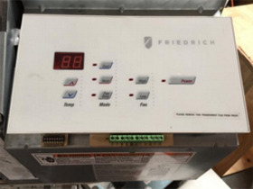
Turn the Power OFF and remove the cover to start the installation
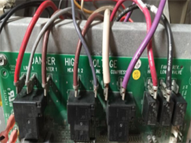
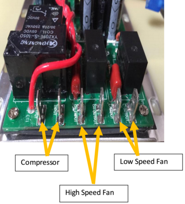
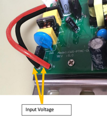
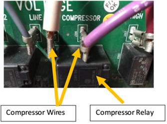
The PTAC-0011 is a PCBA mounted on anodized aluminum base plate energy saving device. It has 6 connectors in one side and 2 connectors on the other side. The 6 connectors are as follows: 2 connectors for Low Speed FAN, 2 connectors for the High Speed FAN and 2 connectors for the Compressor. Please see left photo below. The other side has 2 connectors which supplies the power to the PTAC-0011. Please see right photo below. The PTAC-0011 accepts universal power supply inputs from 90 Vac to 250 Vac, 60 Hz. Either Single phase with L (Live) and N (Neutral) or 2 Phase L1 and L2 will work. See photo below.
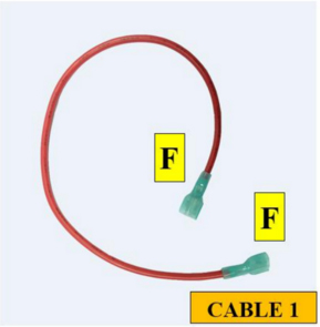
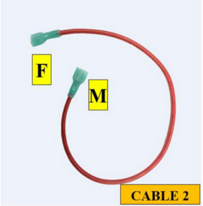
In this step, use the two cable assemblies provided with the PTAC-011 packaging Cable 1 (Red Color): About 10” long with an insulated Female connector on each end. Cable 2 (Red Color): About 10” long with an insulated Female terminal on one end and an insulated Male terminal on the other end.
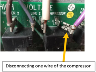
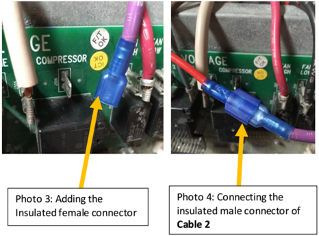
Locate the 2 Compressor relay wires at the PTAC system board. Remove EITHER one of the wires as shown below. Cut off the Female connector attached to this wire. Remove the insulation about 1⁄4” and attached the provided insulated female terminal (14-16 AWG and tab size 1/4"). This wire with the new insulated female terminal (Photo 3) will be connected to insulated male connector of the Red Cable 2(Photo 4). The other end of the Red Cable 2 is connected to the PTAC-0011 Compressor spade terminal. See Photo 5 below.

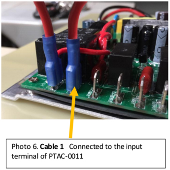
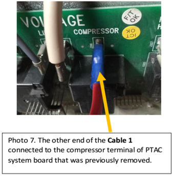
One end of the Red Cable 1 is connected to the PTAC-0011 Compressor input spade terminal (Photo 6). The other end of Black Cable 1 is re-connected back to the spade terminal of the PTAC system board where the original cable was disconnected. See Photo 7.
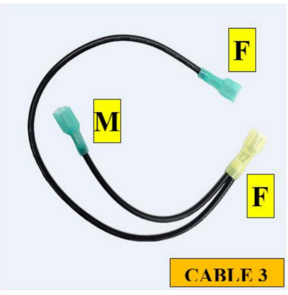
In this step, use the provided Black Cable 3 and only one assembly is required. Black Cable 3: about 10” long with an insulated female connector in one end and insulated female connector at the other end, together with an additional 4” long cable with insulated male terminal the end.
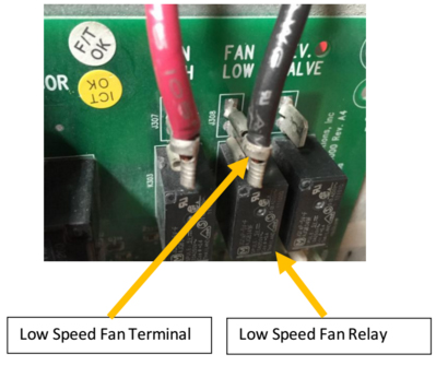
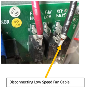
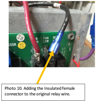
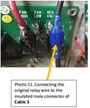
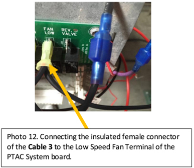
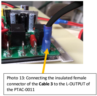
Locate the Low Speed Fan relay line in the PTAC system board. See left photo below. Disconnect that line. Cut the Female connector attached to it, remove the insulation about 1⁄4”. Attach an insulated female terminal (14-16 AWG and tab size 1/4") provided in the package. See Photo 10. This wire with the new insulated female terminal will be connected to the insulated male connector of the Black Cable 3. See Photo 11. The insulated female connector of Black Cable 3 is now connected to the original spade terminal that was previously dis-connected (Photo 12). The other end of the Cable 3 is connected to the L-OUTPUT terminal of the PTAC-0011. See Photo 13.
In this step, use one of cable assembly provided.
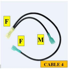
Black Cable 4: about 10” long with an insulated female connector in one end and insulated female connector at the other end together with an additional 4” long cable with insulated male terminal at the end.
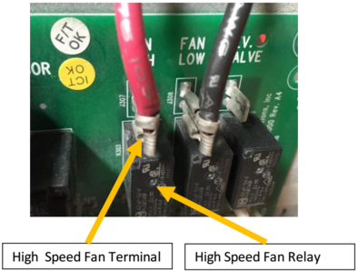
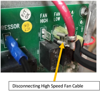
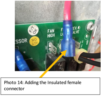
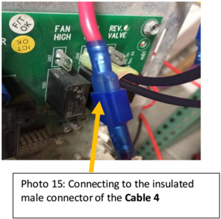
Locate the High Speed Fan relay line. See left photo below. Disconnect that line (Right Photo below). Cut the Female connector attached to it, remove the insulation about 1⁄4”. Install an insulated female terminal (14-16 AWG and tab size 1/4") provided in the package. See Photo 14. This wire with the new insulated female terminal will be connected to the insulated male connector of the Black Cable 4. See Photo 15.
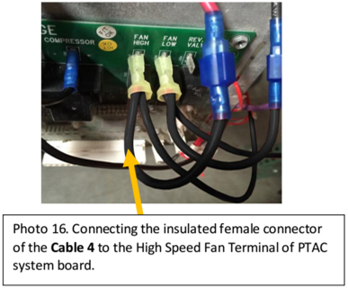
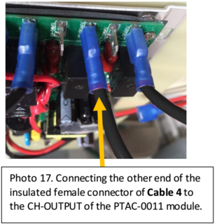
The insulated female connector of Cable 4 is now connected to the original spade terminal that was previously dis-connected (Photo 16). The other end of the Cable 4 is connected to the CH- OUTPUT terminal of the PTAC-0011 module. See Photo 17.
In this step, one cable assembly is required.
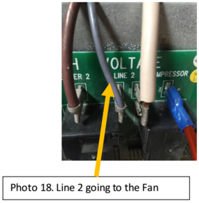
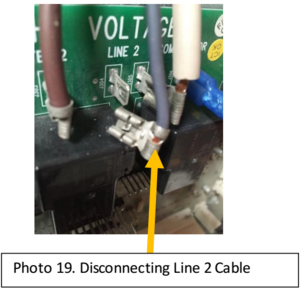
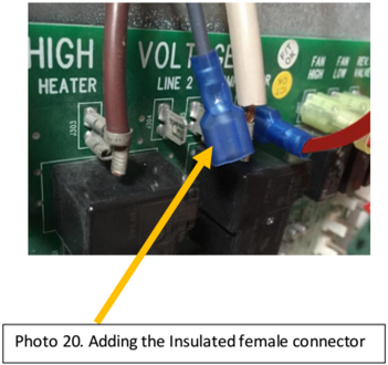
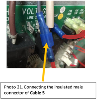
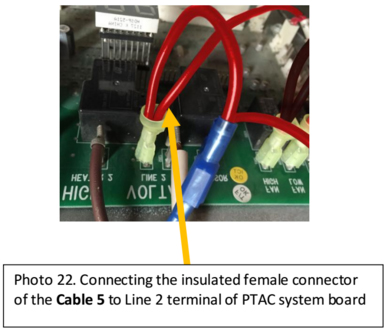
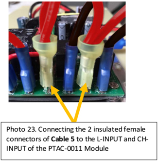
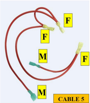
Red Cable 5: about 10” long with an insulated female connector in one end, with an additional 2 insulated female connectors (4” long) and an insulated female connector at the other end, with an additional 4” long cable with insulated male terminal at the end. Locate the common line for the FAN relays (in this case it’s Line 2. See Photo below). Disconnect that line (Photo 19). Cut the Female connector attached to it, remove the insulation about 1⁄4”. Attached an insulated female terminal (14-16 AWG and tab size 1/4") provided in the package. See Photo 20. This wire with the new insulated female terminal will be connected to the insulated male connector of Red Cable 5. See Photo 21. The insulated female connector of Red Cable 5 is now connected to the original spade terminal that was previously dis-connected (Photo 22). The two ends of the Red Cable 5 are connector to the L-INPUT terminal and to the CH-INPUT terminal of the PTAC-0011 module. See Photo 23.
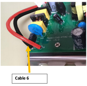
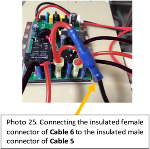
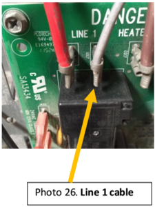
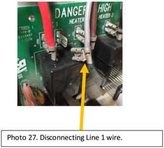
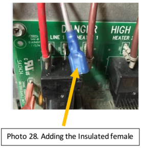
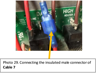
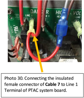
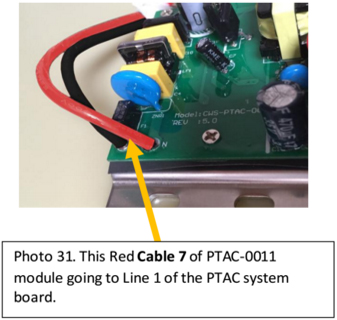
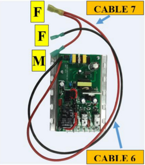
In this step, use the two 10” cables are already soldered to the PTAC-0011 module’s PCB. One cable has an insulated female connector at its end (Black Cable 6). The other cable has at one end an insulated female connector together with an additional insulated male connector about 4”long (Red Cable 7). The end of the Black Cable 6 (insulated female connector) goes to the insulated male connector of Cable 5. See Photo 25. Locate Line 1 on the PTAC system board, and disconnect it from its terminal. See Photo 27. Cut the Female connector attached to it, remove the insulation about 1⁄4”. Attached an insulated female terminal (14-16 AWG and the tab size 1/4") provided in the package. See Photo 28. This wire with the new insulated female terminal will be connected to the insulated male connector of Red Cable 7 (Photo 29). The insulated female connector is connected to terminal where the original cable was connected. See Photo 30 and 31.
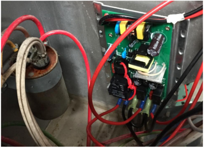
Attach the PTAC-0011 module near to the existing capacitor inside PTAC’s electronic compartment using sheet metal screws through the holes of the base plate flange of PTAC-0011 module. A minimum of 2 screws should be used. The base plate of PTAC- 0011 is completely electrically isolated from the PTAC-0011 module.
Put the cover back and the system is ready to be tested
Coil Winding Specialists, Inc.
353 West Grove Ave.
Orange, CA 92865
1(800) 679-3184