INSTALL THE HVAC-CHIP ON THE 24 VOLTS SECTION OF THE AIR-HANDLER UNIT.
SEE LOWER RIGHT CORNER OF PICTURE ABOVE
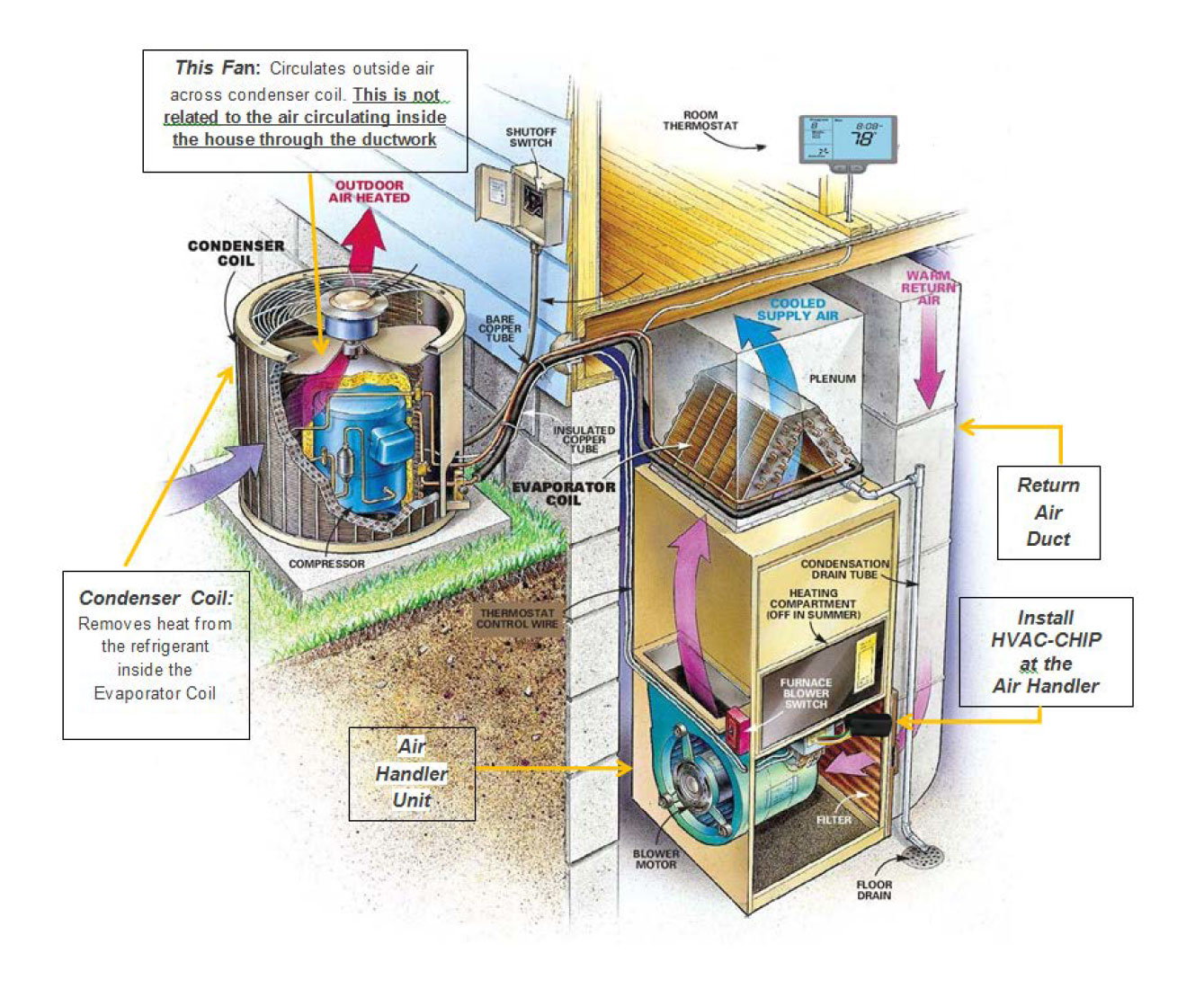
INSTALL THE HVAC-CHIP ON THE 24 VOLTS SECTION OF THE AIR-HANDLER UNIT.
SEE LOWER RIGHT CORNER OF PICTURE ABOVE
Air Handler Unit is a large metal box containing ablower, heating or cooling elements,filterracks or chambers, sound attenuators anddampers. Air handlers usually connect to aduct work ventilation system. In residential homes, it is usually located in the garage and/or in the attic. In commercial buildings, it is typically located on the roof with the compressor
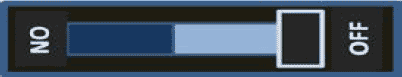
STEP1: Turn OFF power to the main HVAC or Heating/Cooling System by switching the breaker to OFF.
STEP 2: Use a screwdriver to remove the screws and the front metal cover of the Air Handler Unit.
STEP 3: Locate the 24 Volts Panel Terminal Block (or Bus Bar) which is usually on the PCB (Printed Circuit Board) right behind the metal cover. If there is no PCB, identify the wires from the thermostat and to the solenoids by conventional color coding.
STEP 4: Take a photo or make a sketch of the wire connections. Make sure those connections are clear and readable. This will help if reconnection of original wiring becomes necessary.
STEP 5: The HVAC-CHIP works with Conventional, Heat Pump, Gas or Electric HVAC systems.
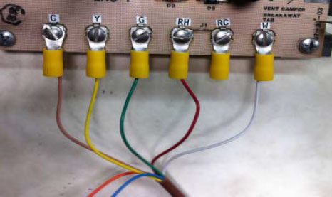
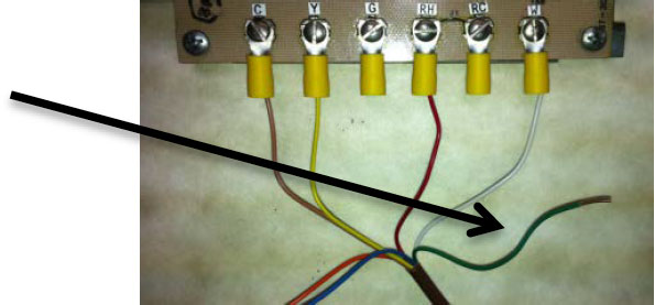
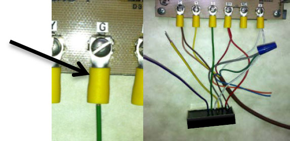
At the Air Handler Unit Control Board, disconnect the Green wire from terminal “G” (blower fan wire). Note that this comes from the thermostat wiring. Internal to the air handler unit, the “G” terminal goes to the blower fan solenoid.
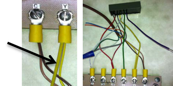
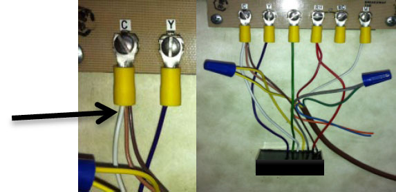
Add the Brown wire of the HVAC-CHIP to the existing wire at terminal “C” which is the 24V Common wire. This means 2 wires at this terminal when the connection is complete.
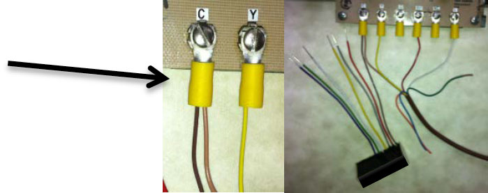
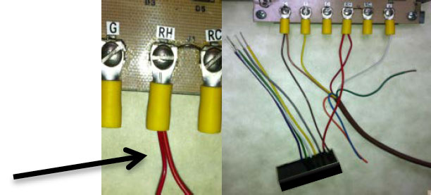
Add the Red wire of the HVAC-CHIP to the existing wire at terminal “RC” or “RH” of the 24V red wire. This means 2 wires at this terminal when the connection is complete.
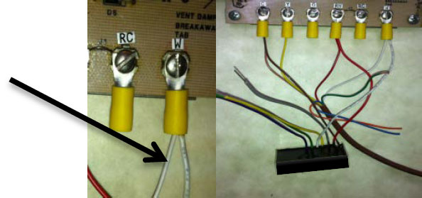
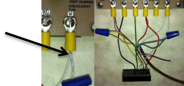
Add the White wire of the HVAC-CHIP to the existing wire at the ”W” terminal (the White wire) of the thermostat wiring. When the connection is complete, there are 2 wires at this terminal.
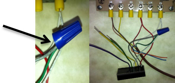
Use a wire nut, connect the Green wire (previously disconnected in step A) to the Gray wire of the HVAC-CHIP. This means that the HVAC-Chip Gray wire is now directly connected to the thermostat’s green terminal.
Connect the Green wire of the HVAC-CHIP to that “G” terminal. Note that only one wire is on this terminal. This means that the HVAC-Chip’s Green wire is now directly connected to the blower fan solenoid wire.
CWS-8THEM-0006X has a temperature probe extending from its back about one inch above the encapsulant. This temperature probe reads the ambient temperature and warns in case the fan extension should be bypassed during extreme heat wave or cold front weather conditions. This is applicable to all normal conventional air conditioning with gas or electric heating and with heat pump. Upon completion of installation, any unconnected wires may be capped with a wire nut.
STEP 6: Installation is completed. Be sure the connections are correct and tight . Turn the power back ON
Run the “TEST INSTRUCTIONS” listed in www.hvac-chip.com to ensure the connections are done correctly.
Note: The fan extension is based on an intelligent feedback algorithm and not based solely on the current compressor run time. It is based on data collected over many previous compressors on cycles and off cycles to predict how long the fan should be extended to maximize the energy savings. The temperature probe measures the ambient temperature where the HVAC CHIP is located or installed, and will bypass the fan extension during extreme weather conditions to prevent blowing in hot air during heat wave in the summer or blowing in cold air during a cold front in the winter.
Coil Winding Specialists, Inc.
353 West Grove Ave.
Orange, CA 92865
1(800) 679-3184